

How Does a Breadboard Work?
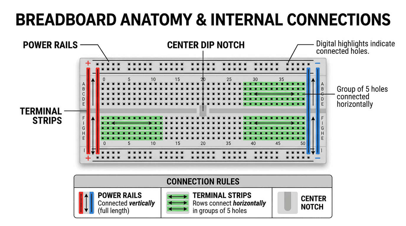
A breadboard is a reusable plastic board with rows of tiny holes connected by internal metal clips. Components push into the holes to form circuits without soldering. The centre rows connect horizontally in groups of 5. The side rails run vertically for power and ground. Understanding these internal connections is the only thing you need to learn before building your first circuit.
This guide covers how a breadboard is wired inside, how to connect power, how to place components correctly, and the mistakes that catch out every beginner. By the end, you'll build a working LED circuit on a breadboard connected to your Arduino. If you haven't bought your kit yet, see our getting started with Arduino roadmap.

What Is a Breadboard?
A breadboard (also called a solderless breadboard) is a prototyping tool that lets you build and test electronic circuits without soldering. You push component legs and wire ends into the holes, and spring-loaded metal clips inside the board grip them and make electrical contact. You can build a circuit in minutes, test it, swap components, and take it apart without damaging anything.
The name comes from the early days of electronics, when hobbyists literally nailed components onto wooden bread-cutting boards. Modern breadboards are plastic and far more practical, but the name stuck.
Breadboards are included in every Arduino starter kit from Kunkune. If you need a breadboard on its own, Kunkune stocks the Prototype Breadboard Kit which includes a full-size breadboard, 65 jumper wires, and a power module for £5.90.
What Are the Different Parts of a Breadboard?
A standard breadboard has three distinct areas. Each one is wired differently inside, and mixing them up is the most common beginner mistake.
Terminal Strips (The Centre Area)
The large central area is where you place your components. It is divided into two halves by a gap running down the middle (called the DIP notch). On each side, the holes are arranged in rows. Within a single row on one side, all 5 holes are connected together horizontally by a metal clip underneath. Row 1 holes a, b, c, d, e are all joined. Row 1 holes f, g, h, i, j on the other side are also joined — but the two sides are not connected to each other across the gap.
This gap exists so you can place integrated circuit (IC) chips across it. Each pin of the chip sits in a different row, with no short circuits between pins.
Power Rails (The Side Strips)
The two long strips running along each edge of the board are the power rails. These are marked with red (+) and blue (−) lines. Unlike the centre rows, the power rails connect vertically along the full length of the board.
You connect your power supply to the rails, then run short jumper wires from the rails to whichever rows need power or ground. This means every component on the board can access power without running wires all the way back to the Arduino.
Important: On some full-size breadboards, the power rail has a break in the middle. The top half and bottom half are not connected. If your circuit works on one half of the board but not the other, bridge the gap with a short jumper wire.
The DIP Notch (Centre Gap)
The groove running down the middle separates the left half (columns a–e) from the right half (columns f–j). It's exactly the right width for standard DIP-package chips. The gap ensures that pins on opposite sides of a chip are electrically isolated from each other.
What Size Breadboard Do I Need?
Breadboards come in three common sizes. For Arduino projects, a half-size board handles most beginner builds.
Mini breadboard (170 tie points): Tiny and portable. No power rails on most models. Good for very small circuits or mounting alongside a sensor in a tight space.
Half-size breadboard (400 tie points): The standard beginner choice. Two power rails and enough rows for an Arduino Nano plus several components. Fits comfortably on a desk. This is what most starter kits include.
Full-size breadboard (830 tie points): Twice the rows of a half-size board. Two complete sets of power rails. Best for complex circuits with multiple ICs or lots of wiring. You can also interlock multiple boards side by side using the notches on their edges.
How Do I Connect Power to a Breadboard?
When using a breadboard with an Arduino, the Arduino itself provides power. Run a jumper wire from the Arduino's 5V pin to the red (+) rail on the breadboard. Run another jumper wire from the Arduino's GND pin to the blue (−) rail. Every component on the board can now access 5V and ground from those rails.
Use colour-coded jumper wires to keep things clear: red for power, black for ground, and other colours for signal connections. This is not electrically necessary — all jumper wires carry current the same way — but it makes debugging much easier when you can visually trace which wire goes where.
If your circuit needs both 5V and 3.3V, use one side's power rail for 5V and the other side's rail for 3.3V. The Arduino has both a 5V and a 3.3V output pin.
How Do I Place Components on a Breadboard?
Push component legs gently but firmly into the holes. The internal clips grip the legs with enough force to hold them in place, even if you turn the board upside down. If a component won't fit, the legs may be too thick — don't force it.
The key rule: to connect two components together, their legs must be in the same row on the same side of the centre gap. If a resistor leg is in row 10, column c, anything else plugged into row 10, columns a, b, d, or e is electrically connected to that resistor leg.
To keep components separate, place their legs in different rows. Each row is an independent connection point.
Placing an LED
LEDs have a longer leg (anode, positive) and a shorter leg (cathode, negative). Push the LED into the breadboard with each leg in a different row. The longer leg goes toward the power side of your circuit, the shorter leg toward ground. If you get it backwards, the LED simply won't light — it won't be damaged, just flip it around.
Placing a Resistor
Resistors have no polarity — either leg can go in either direction. Bend the legs to a suitable width and push them into two different rows. Whatever shares a row with one leg is connected to that end of the resistor.
Placing an IC Chip
Straddle the chip across the centre gap. Each pin sits in its own row, fully isolated from the pin on the opposite side. A small notch or dot on the chip marks pin 1. Always orient the chip the same way when following a tutorial diagram.
How Do I Build My First Breadboard Circuit?
This circuit blinks an LED using an Arduino, the same project from Step 5 of the Arduino roadmap. Here's the full wiring breakdown.
What You Need
- Arduino Uno-compatible board
- Half-size breadboard
- 1× LED (any colour)
- 1× 220Ω resistor
- 2× male-to-male jumper wires
Wiring Steps
- Push the LED into the breadboard — longer leg in row 10, shorter leg in row 11
- Push one leg of the 220Ω resistor into row 10 (same row as the LED's longer leg). Push the other leg into row 15.
- Run a jumper wire from row 15 to pin 9 on the Arduino
- Run a jumper wire from row 11 (where the LED's shorter leg is) to the blue (−) power rail
- Run a jumper wire from the blue (−) power rail to a GND pin on the Arduino
The circuit path is: Arduino pin 9 → jumper wire → resistor → LED → jumper wire → GND. Current flows from pin 9, through the resistor (which limits current), through the LED (which lights up), and back to ground.
Upload the Blink sketch from your Arduino IDE setup (change the pin number to 9), and the LED blinks.
What Are the Most Common Breadboard Mistakes?
Every beginner makes at least one of these. Knowing them in advance saves hours of frustration.
Components in the wrong row. If two component legs are in the same row, they're connected. If they're in different rows with no jumper wire between them, they're not connected. Double-check that your wiring matches the circuit diagram row by row.
LED inserted backwards. The longer leg is positive (anode). If the LED doesn't light, flip it around. A reversed LED won't be damaged — it just won't conduct current.
Forgetting the ground connection. Every circuit needs a complete path from power to ground. If you connect the LED to pin 9 but forget the jumper wire from the LED's negative row back to GND, nothing happens.
Power rail break on full-size boards. Some full-size breadboards split the power rail into two halves. Components on the lower half won't get power unless you bridge the gap with a jumper wire.
Loose connections. If a jumper wire or component leg isn't pushed in far enough, the metal clip inside won't grip it properly. The circuit will be intermittent — sometimes working, sometimes not. Push components in until you feel them click into place.
Using the wrong wire gauge. Breadboards work best with 22 AWG (0.65 mm diameter) solid-core wire. Stranded wire frays and doesn't grip well. If you're using pre-made jumper wires from a starter kit, they're already the right gauge.
When Should I Stop Using a Breadboard?
Breadboards are for prototyping and learning — not permanent projects. Move to a soldered solution when your circuit is finalised and you want it to last. The options include stripboard (perfboard with copper strips), custom PCBs (you can order them cheaply from services like JLCPCB), or simply soldering wires directly between components.
You'll know it's time to move on when your breadboard circuit works reliably and you want to put it inside an enclosure, mount it to a wall, or use it somewhere that vibration or movement could dislodge a connection.
For most Arduino beginners, breadboards are the right tool for the first 6–12 months of projects. There's no rush to move to soldering.
Frequently Asked Questions
The Bottom Line
A breadboard is the single most important tool for learning electronics. Once you understand that centre rows connect horizontally in groups of 5 and power rails connect vertically, you can build any beginner circuit. Grab a breadboard from your starter kit, wire up the LED circuit above, and you're ready for the next step — reading sensors and adding displays.