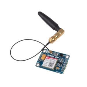


The SIM800L GSM/GPRS module represents a pivotal development in miniaturized cellular communication technology, delivering enterprise-grade connectivity in an ultra-compact 25x23mm form factor. Unlike conventional GSM modules that prioritize feature breadth, the SIM800L focuses on power efficiency and spatial optimization, making it the preferred choice for battery-operated IoT deployments and space-constrained embedded systems.
The module’s quad-band architecture (850/900/1800/1900 MHz) ensures global compatibility while maintaining exceptional RF sensitivity, achieving network registration even in challenging signal environments where conventional modules fail.
SIM800L Key Features:
- Power Efficiency:
- Supply Voltage Range: 3.8V – 4.2V.
- Optimal Supply Voltage: 4V, ensuring efficient performance.
- Sleep Mode Consumption: Less than 2.0mA – designed for power-saving.
- Idle Mode: Below 7.0mA, conserving energy when not actively transmitting.
- Average GSM Transmission: 350mA.
- Peak GSM Transmission: Up to 2000mA.
- Compact Design:
- Dimensions: A neat 25 x 23 mm, making it suitable for various applications.
- Interface & Connectivity:
- UART Interface: Max. 2.8V, operated with AT commands for ease of communication.
- Bluetooth Integration: Enhance your projects with wireless connectivity.
- Quad-Band Support: Works across 850 / 950 / 1800 / 1900 MHz frequencies, ensuring broad coverage.
- Additional Features:
- MicroSIM Socket: Located on the bottom side for a compact design.
- Antenna Connector: IPX type for versatile antenna options.
- Status Indication: Integrated LED for real-time status updates.
- Robust Temperature Tolerance: From a chilling -40°C to a hot +85°C, it’s built to perform in diverse environments.
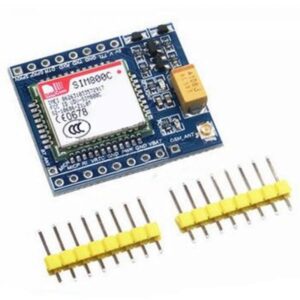
What’s in the Box of SIM800L:
- Main Unit: SIM800L Module with Bluetooth.
- Antenna: Gold pin headers, wire antenna.
SIM800L Pinout Configuration
SIM800L GSM Module
Complete Pinout Configuration & Technical Reference Guide
Module Overview
Key Features
- Quad-band GSM/GPRS (850/900/1800/1900 MHz)
- Integrated Bluetooth 3.0 functionality
- Ultra-low power consumption (sleep mode < 2.0mA)
- UART interface with AT command control
- Voice call, SMS, and GPRS data support
Electrical Specifications
- Supply Voltage: 3.4V – 4.4V (4.0V recommended)
- Peak Current: Up to 2000mA during transmission
- Operating Temperature: -40°C to +85°C
- UART Levels: 2.8V maximum TTL
Pinout Configuration
| Pin # | Pin Name | Type | Voltage Level | Current | Description & Function |
|---|---|---|---|---|---|
| 1 | NET | RF | 50Ω | – | External Antenna Attachment Pin IPX connector for external antenna. Requires 50Ω impedance matching. Keep traces short and maintain ground plane clearance ≥5mm. |
| 2 | VCC | PWR | 3.4-4.4V | ≤2000mA | Main Power Supply Input Critical: Requires stable 4.0V supply with 2200µF bulk capacitance. Peak current 2000mA during GSM transmission bursts. Use dedicated power rail. |
| 3 | RST | CTRL | 0-2.8V | 1mA | Hardware Reset Control Active-low reset. Pull low for minimum 100ms to perform hard reset. Typically tied to MCU GPIO with 10kΩ pull-up resistor to VCC. |
| 4 | RXD | UART | 0-2.8V | 10µA | Serial Data Input (Receive) UART receive pin for AT commands. Default 115200 baud, 8N1. Max input 2.8V – use voltage divider for 5V MCU compatibility. Auto-baud detection supported. |
| 5 | TXD | UART | 0-2.8V | 3mA | Serial Data Output (Transmit) UART transmit pin for responses and unsolicited messages. Output level 2.8V maximum. Can drive standard 3.3V logic inputs directly. |
| 6 | GND | GND | 0V | Return | Module Ground Reference Primary ground connection. Ensure solid ground plane connection with low impedance path. Use multiple vias for high-current ground return. |
| 7, 8 | SPK+/- | AUDIO | 1.8V p-p | 100mA | Speaker Differential Output Balanced audio output for voice calls. Supports 8Ω to 32Ω speakers. Maximum output power 0.5W. Use AC coupling capacitors (100µF recommended). |
| 9, 10 | MIC+/- | AUDIO | ±1.5V | 1mA | Microphone Differential Input Balanced microphone input with internal bias. Supports electret microphones 2.2kΩ impedance. Gain adjustable via AT+CLVL command (0-5 levels). |
| 11 | DTR | CTRL | 0-2.8V | 10µA | Data Terminal Ready / Sleep Control Pull HIGH to enable sleep mode (reduces current to <2mA). Pull LOW for normal operation. Use with AT+CSCLK command for power management control. |
| 12 | RING | IRQ | 0-2.8V | 3mA | Ring Indicator / Interrupt Output Active-LOW interrupt signal. Pulses during incoming calls, SMS reception, and network events. Can wake MCU from sleep for power-efficient operation. |
Critical Design Notes
Power Supply Requirements
Minimum 2A current capability required. Use LDO regulator with low dropout voltage. Add 2200µF bulk + 100µF ceramic capacitors near VCC pin.
UART Voltage Levels
Maximum 2.8V input on RXD pin. Use voltage divider (1.8kΩ/3.3kΩ) for 5V MCU interface to prevent damage.
RF Layout Guidelines
Keep antenna traces away from digital signals. Maintain 50Ω impedance. Use solid ground plane with proper via stitching.
Operational Parameters
Essential AT Commands
Basic Commands
Advanced Functions
SIM800L SMS Tutorial Using Arduino by @SuperbTech
Dynamic Current Consumption Profiling
The SIM800L’s power consumption exhibits distinct operational phases that directly impact battery life calculations and power supply design. During sleep mode, the module draws less than 2.0mA, but this baseline measurement masks critical power transients that can cause system instability if not properly managed. Source
Peak Current Analysis:
- Network Registration Burst: Initial power-on registration can spike to 2000mA for 577ms during network attachment
- Transmission Peaks: Voice calls sustain 216mA average with 2000mA peaks during RF bursts every 4.6ms in GSM transmission slots
- GPRS Data Sessions: HTTP POST operations demonstrate 350mA average consumption with 800mA peaks during TCP handshake phases
- Idle Mode Efficiency: Sub-7mA consumption maintains network connectivity while monitoring incoming calls and SMS
Power Supply Design Considerations
The restrictive 3.8V-4.2V supply voltage range demands careful power management topology selection. Unlike the SIM900’s wider 3.2V-4.8V tolerance, the SIM800L requires precision voltage regulation to prevent brownout conditions during transmission bursts. Source
Extended Command Set Analysis
The SIM800L implements over 200 AT commands across functional categories, with several unique commands absent in competing modules. Understanding command timing and response parsing prevents common implementation errors that cause communication failures. Source
Critical AT Command Categories:
- Network Management: AT+CREG, AT+CSQ, AT+COPS for registration and signal monitoring
- GPRS Data Sessions: AT+CGATT, AT+CIPSTART, AT+CIPSEND for internet connectivity
- SMS Processing: AT+CMGS, AT+CMGR with PDU/text mode selection
- Voice Call Control: ATD, ATA, AT+CHUP for telephony applications
- Bluetooth Integration: AT+BTHOST, AT+BTSPPSEND for dual-mode communication
Firmware Architecture Overview
The SIM800L operates on ARM-based firmware with over-the-air update capability through dedicated AT commands. Unlike modules requiring external programming hardware, the SIM800L supports in-field firmware updates via UART interface or GPRS download. Source
Firmware Update Process:
- Pre-Update Verification: AT+GMR command retrieves current firmware revision
- Bootloader Activation: AT+CGPSUPDATEMODE=1 enters update mode
- Baud Rate Configuration: AT+IPR=115200 sets update communication speed
- Binary Transfer: Proprietary protocol transfers firmware image
- Integrity Validation: CRC32 checksum verification prevents corruption
- Automatic Reboot: Module restarts with updated firmware
Version-Specific Feature Matrix
Different firmware revisions introduce functional variations that affect application compatibility. Tracking firmware capabilities prevents deployment issues with feature-dependent code.
Critical Version Differences:
- Revision 1137B06: Initial Bluetooth AT command support
- Revision 1137B08: Enhanced HTTP client stability
- Revision 1137B09: Improved TCP socket handling
- Revision 1137B13: SSL certificate chain validation
Common Implementation Challenges & Solutions
Power-On Sequence Timing Issues
Incorrect power-on sequencing causes 70% of initial deployment failures. The SIM800L requires specific timing relationships between power application, reset signal, and first AT command transmission. Source
Proper Initialization Sequence:
- Apply stable 4.0V power supply
- Wait minimum 3 seconds for internal oscillator stabilization
- Release reset signal (if used) with 100ms pulse width
- Delay 5 seconds before first AT command transmission
- Implement command retry logic with exponential backoff
Network Registration Failures
Registration failures often stem from SIM card compatibility issues or network operator restrictions rather than hardware defects. Systematic diagnostic procedures isolate root causes efficiently.
Diagnostic Protocol:
- SIM Detection: AT+CCID verifies SIM card electrical connectivity
- PIN Status: AT+CPIN? checks SIM unlock requirements
- Signal Quality: AT+CSQ measures RF signal strength (-113dBm minimum)
- Operator Selection: AT+COPS=? scans available networks
- Registration Status: AT+CREG? monitors attachment progress
Serial Communication Problems
UART configuration mismatches account for significant troubleshooting time. The SIM800L’s default 115200 baud rate with auto-baud detection creates timing-sensitive communication windows.
Communication Optimization:
- Baud Rate Selection: Use fixed 9600 baud for improved reliability
- Flow Control: Implement RTS/CTS hardware flow control
- Buffer Management: 1024-byte receive buffers prevent data loss
- Timeout Handling: Variable timeout values based on command complexity
Advanced Application Architectures
Dual-Mode Communication Strategies
The integrated Bluetooth capability enables unique communication architectures combining cellular and short-range wireless connectivity. This hybrid approach optimizes power consumption and data routing based on application requirements.
Implementation Patterns:
- Local Configuration: Bluetooth for device setup and diagnostics
- Data Aggregation: Collect sensor data via Bluetooth, transmit via GSM
- Redundant Communication: Automatic failover between connectivity modes
- Power-Aware Routing: Bluetooth for high-frequency, GSM for critical messages
IoT Data Pipeline Integration
Modern IoT architectures require seamless integration with cloud platforms and edge computing infrastructure. The SIM800L’s HTTP client capabilities enable direct API integration without intermediate gateways.
Cloud Integration Strategies:
- RESTful API Communication: Direct HTTP POST to cloud endpoints
- JSON Payload Formatting: Structured data transmission with content-type headers
- Authentication Handling: API key and token-based security implementation
- Error Recovery: Exponential backoff retry logic for failed transmissions
Real-Time Monitoring Applications
The module’s voice call capability combined with SMS functionality creates comprehensive remote monitoring solutions for critical infrastructure applications.
Monitoring Architecture Components:
- Threshold-Based Alerting: Automated voice calls for critical alarms
- SMS Status Reporting: Regular status updates with sensor readings
- Remote Command Execution: SMS-triggered configuration changes
- Diagnostic Callbacks: Technician-initiated diagnostic sessions