
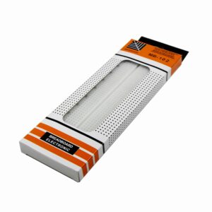
Breadboards and jumper wires for prototyping
Breadboards and wires are essential for electronics prototyping, allowing you to test circuits without soldering. Whether you’re a beginner or a pro, find the right breadboard for your projects with our diverse selection in Kunkune.
Showing all 9 resultsSorted by price: high to low

Showing all 9 resultsSorted by price: high to low
What Are Breadboards and Wires?
Breadboards and wires are important tools in electronics, providing a flexible base for building electronic circuits without soldering. These devices allow both hobbyists and professionals to quickly build and check different electronic components such as integrated circuits, capacitors, and transistors. Breadboards are equipped with contact points and spring contacts that facilitate easy insertion and removal of components.
Breadboards are available in various sizes, offering numerous connection points and strips to suit different electronic projects. Jumper wires are used to connect different components, whether for home automation systems or testing LED circuits or adjustable timers.
Why Are Breadboards and Wires Used in Electronics?
Breadboards and wires are popular in electronics because they allow for quick and easy testing of circuits without soldering. This is important for both beginners and experienced engineers working on DIY projects.
They provide a reusable platform where you can insert components such as transistors, LEDs, and other electronic components, allowing for easy adjustments and testing of different configurations. The solderless breadboard design enhances flexibility, enabling users to experiment with various circuit designs without permanent alterations.
Types of Breadboards and Wires
There are different types of breadboards and wires made for various electronic testing purposes, each with specific features that improve ease of use and functionality, such as powered breadboards with built-in voltage regulators for home projects.
Solderless breadboards are particularly popular due to their ease of use, allowing users to quickly insert and remove electronic components without the hassle of soldering. They include power rails and bus rails to streamline the connection of multiple electronic components.
Solderable breadboards offer a more permanent solution for those looking to create durable circuits, while jumper wires and hookup wires provide the necessary connections between components, ensuring a reliable and efficient setup for various electronic projects.
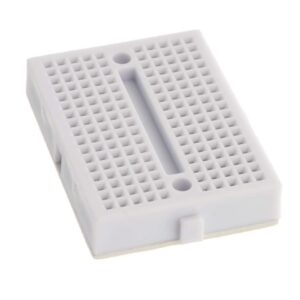
Solderless Breadboards
Solderless breadboards are designed for easy insertion and removal of electronic components, making them ideal for DIY projects and quick prototyping, as they allow users to test circuit designs without permanent changes or soldering.
This new method of circuit design makes it simple for both beginners and experienced hobbyists to create, change, and fix their electronic projects. With a simple layout typically composed of rows and vertical power rails, a breadboard enables users to create a variety of circuits.
- For beginners, starting with simple LED circuits becomes both feasible and enjoyable.
- Experienced users might work on detailed projects, such as connecting microcontrollers.
Solderless breadboards are extremely useful, allowing people to try out ideas and build their skills in electronics with greater confidence.
Solderable Breadboards
Solderable breadboards provide a permanent solution for circuit construction, allowing users to solder electronic components directly onto the board, thereby enhancing durability and stability in prototyping circuits.
This method ensures components stay in place and extends the lifespan of projects by reducing the chance of loose connections. By ensuring a solid mechanical and electrical bond, these boards are ideal for:
- long-term installations
- educational projects
- hobbyist pursuits
where performance cannot be compromised. The soldering process typically involves placing the component leads through designated holes and melting solder to create strong connections. Suitable examples of advanced projects that benefit from solderable breadboards include robotics controllers, sensor arrays, and custom audio amplifiers. These applications need to be very reliable and accurate, so using solderable options is necessary for good results.
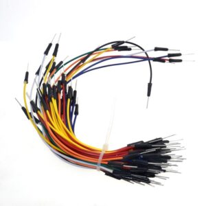
Jumper Wires
Jumper wires are essential for connecting various electronic components on breadboards, providing a flexible and efficient way to complete circuit connections.
These wires come in different configurations, including male-to-male, male-to-female, and female-to-female, each serving specific purposes in circuit assembly. For instance, male-to-male jumpers are typically used to connect components directly to breadboard rows, while male-to-female variants allow for connections between components and Arduino or Raspberry Pi pins. Lastly, female-to-female wires can be useful for extending or joining connections when required.
- Organising these wires properly can significantly improve circuit management.
- Consider colour-coding wires to easily distinguish between different connections.
- Using wire ties or clips can help keep them bundled together and prevent tangling.
By keeping the layout organised, the circuit looks neater and is simpler to fix and change as projects grow.
Hookup Wires
Hookup wires are used to make connections between breadboards and external components, ensuring a reliable and secure circuit setup for various electronic projects.
These wires are important for testing and final designs, allowing engineers and hobbyists to create detailed circuits without permanent soldering. In contrast, jumper wires serve a unique role, typically used for making temporary connections in test setups.
- Applications: While hookup wires are often used in circuit boards and permanent installations, jumper wires excel in quick adjustments and troubleshooting.
- Wire gauge also plays a critical role; a lower gauge indicates a thicker wire, capable of carrying more current, which is essential for high-power applications.
Insulation is equally important as it ensures safety by preventing short circuits, making certain that connections remain both effective and safe throughout the project.
What Are the Benefits of Using Breadboards and Wires?
Using breadboards and wires provides many advantages for electronics enthusiasts. These tools make it easy to test circuits, reuse components, and modify designs. They are important for both beginners and experts in DIY projects.
The option to change circuits without soldering allows people to try new ideas quickly and easily. High-quality connectors and robust designs ensure reliability in various electronics environments, from schools to home automation systems. Such setups are ideal for projects like a mini weather station or a light-sensitive circuit.
Easy Prototyping
Breadboards significantly simplify the prototyping process, allowing users to quickly assemble and test electronic circuits without the need for soldering.
This tool is important for hobbyists and professionals because it allows quick changes to designs, which is helpful for fixing problems or improving how things function. By simply connecting components through jumper wires and placing them in aligned rows, the circuit can be modified in real-time without any irreversible actions. Projects such as:
- Simple LED circuits, where users experiment with different resistor values and configurations to achieve various lighting effects.
- Integrated circuit designs Developers can create, test, and enhance chips and components before assembling them.
This flexibility makes breadboards a very useful tool for inventing and creating in electronics.
Reusability
One of the primary advantages of breadboards is their reusability; components can be easily inserted and removed, allowing users to repurpose materials for different projects.
This flexibility is extremely useful, especially for hobbyists and professionals who often work on several experiments at the same time. Users can change their setups to test different circuits, allowing them to use the same components in many electronic designs.
For instance, when transitioning from a basic LED circuit to a more complex microcontroller project, rather than purchasing new components, one can simply reconfigure the existing layout.
- This leads to significant cost savings, as funds are not wasted on disposable materials.
- Reducing electronic waste is important for protecting the environment.
Therefore, the ability to interchange components encourages creativity and innovation while promoting eco-friendly practices in electronics.
Flexibility
Breadboards provide great flexibility in circuit design, allowing electronics enthusiasts to easily change their projects and adapt to new ideas.
This flexibility makes prototyping easier and supports experimenting with different components. For instance, when a user integrates sensors or switches, they can quickly rearrange the circuit layout without soldering, saving time and effort.
- If the initial concept requires additional features, such as adding LEDs for visual feedback, the design can be expanded by simply inserting more components.
- Similarly, if the user wishes to make the project smaller for a simpler application, removing unnecessary components is just as straightforward.
This method encourages creativity and enhances learning because individuals can see the immediate effects of their changes, whether they are constructing electronic circuits or experimenting with DIY projects.
Ultimately, the flexibility of breadboards is essential in continuously improving and creating new electronic solutions.
Cost-effective
Using breadboards and wires is a cost-effective solution for building and testing electronic circuits, significantly reducing the need for expensive soldering equipment and materials. A breadboard can be used to set up various circuits, such as an LED circuit or even a DIY electric piano.
The affordability of breadboards means that hobbyists and professionals can experiment without the fear of wasting costly components. Instead of committing to permanent connections, users can easily make adjustments, test different configurations, like an LED circuit or a voltage doubler, and learn through trial and error at little to no extra cost.
This flexibility boosts creativity and helps quickly create models of ideas. With breadboards, projects can be changed quickly, allowing for a step-by-step process that can result in improved designs. By avoiding the hassle of soldering, individuals can focus more resources on actually developing their concepts, whether it’s a simple LED circuit or a complex sound generator, rather than spending time fixing mistakes.
- Lower initial setup costs
- Quick assembly and disassembly
- Reusability of components
In essence, utilising breadboards can significantly lower the overall expense of electronics projects, making them accessible for anyone with a passion for innovation.
How to Choose the Right Breadboard and Wires for Your Project, like a 555 Timer IC circuit?
Selecting the right breadboard and wires for your electronic project is important for effective prototyping and constructing a functioning circuit. You should consider factors such as size, layout, and the number of connection points available.
The ideal breadboard should correspond to the scale of your project while accommodating the electronic components you intend to use, from basic resistors to more complex integrated circuits like a 555 Timer IC or 4017 IC. Choosing the appropriate wire gauge and length will enhance the reliability of the connections.
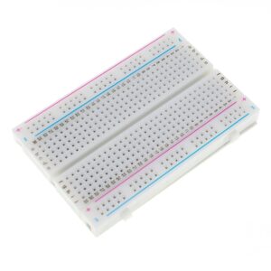
Size and Layout
The size and layout of a breadboard can significantly impact your project, making it important to choose a board that accommodates all your electronic components comfortably.
When starting a new project, it is important to know the different breadboard sizes and layouts. Each type is suited for specific design needs depending on how complicated your project is. A smaller breadboard might suffice for simple circuits, but as projects evolve, making room for extra parts is very important. This knowledge improves the current design and makes future changes easier. Consider if you need a compact design for space-saving or a larger one for more components.
Therefore, consider the following aspects when selecting a breadboard:
- Future Expansion: Select a size that allows room for adding new components later.
- Component Variety: Make sure there is plenty of room for different parts like resistors, capacitors, and integrated circuits.
- Accessibility: A well laid-out breadboard enables easier wiring and troubleshooting.
Careful planning of breadboard size and layout can help make your project both workable and expandable.
Number of Connection Points
The number of connection points on a breadboard directly affects the complexity of your circuit, as having more connection points allows for greater flexibility in arranging electronic components.
This increased flexibility significantly enhances the user’s ability to create elaborate designs without the constraints typically associated with fewer connection points. For instance, with more connections available, one can easily implement complex circuit configurations or experiment with various component placements that might be cumbersome on a smaller board, such as an extensive circuit diagram for a project.
Having ample connection points enables constructors to:
- Test diverse setups with minimal reconfiguration
- Add more parts like sensors and ICs without losing clarity
- Fix and change designs more quickly
This feature supports academic study of electronic principles and allows engineers to easily create new solutions.
Wire Gauge and Length for Effective Prototyping
Choosing the correct wire size and length is important for ensuring you have reliable connections between components on your breadboard, especially for detailed electronic projects like a 555 Timer IC or infrared receiver circuit.
Understanding how the thickness of a wire affects the amount of current it can carry and its resistance is crucial for any electronic project. Using a wire that is too thin can result in increased resistance, leading to potential overheating and voltage drops, especially as the length of the wire increases. For example, using thin wires in a sound generator or DIY electric piano may cause issues with performance.
Longer wire runs can degrade signal integrity, which is particularly critical in sensitive applications such as audio or high-speed data transmission. To avoid these issues, it is advisable to match wire specifications to project requirements.
- For high current applications, opt for a thicker gauge wire to handle the load.
- Shorter distances may allow for thinner wires, but keep a close eye on the total resistance.
- When working with digital signals, consider using twisted pairs to minimise interference.
- For connections using LED components, ensure wires are of adequate thickness to prevent voltage drops.
Material and Durability for Long-Lasting Performance
The material and durability of a breadboard can greatly influence its performance and longevity in various electronics environments. For example, using a breadboard made from high-quality materials like phosphor bronze or copper can enhance connection reliability.
For instance, breadboards constructed from high-quality thermoplastic can withstand significant wear and tear, making them ideal for projects requiring frequent modifications. In contrast, those made from lower-grade materials may suffer from poor connectivity and rapid degradation. Breadboards utilising phosphor bronze or copper enhance electrical conductivity and longevity.
Choosing the right breadboard material is very important for achieving the best results in prototype development.
- Plastic breadboards: Lightweight and affordable, suitable for beginners.
- Metal breadboards: Provide improved strength and increased electrical flow, ideal for detailed projects.
- Composite breadboards: Combine the benefits of both types, providing resilience and functionality.
Ultimately, when selecting a breadboard, consider project requirements, including anticipated modifications and environmental conditions, to choose the most effective option for your needs.
Tips for Using Breadboards and Wires
To get the most out of breadboards and wires in your electronic projects, it is important to follow best practices for setup and use. This will greatly improve the quality and reliability of your connections.
Keeping your breadboard organised and ensuring that all components fit snugly into the contact points will prevent connection issues and improve the overall performance of your prototyping circuit. Using different wire colours helps to identify connections and fix any problems in the circuit.
Keep the Breadboard Clean
Maintaining a clean breadboard is necessary for maintaining reliable connections and the best performance of your electronic projects.
Dust and debris can interfere with electrical connections between components, causing unpredictable behaviour and making problem-solving difficult. It’s essential to keep the workspace organised and remove any particles regularly.
Here are some effective cleaning tips and best practices for maintaining a tidy environment:
- Use a soft brush or compressed air to gently remove dust from the surface.
- Wipe down the board with a lint-free cloth slightly dampened with isopropyl alcohol for deep cleaning.
- Store components in labelled containers to avoid clutter.
- Regularly inspect your tools and materials for any leftover residue.
By following these habits, one can ensure their projects proceed without sudden interruptions.
Use Different Colours for Wires
Using different colours for your wires improves the appearance of your breadboard setup and helps in organising and recognising connections better. This approach helps you understand your circuit better, making it simpler to fix issues as they arise and reducing design errors. This is particularly advantageous for DIY projects where clarity can significantly reduce troubleshooting time.
Colour coding is a very useful method in circuit design. It allows one to quickly analyse and debug circuits, as the colours can signify specific functions or characteristics of the wires.
- Red typically indicates positive voltage.
- Black usually represents earth or negative connections.
- Blue can be used for signals, while yellow is often reserved for power.
Using such established colour schemes enables easier identification and maintenance, especially in complex projects.
When troubleshooting, for instance, an engineer can immediately locate which wire corresponds to the power supply, thus expediting the process of isolating faults and applying corrections. This method is particularly useful when dealing with complex projects such as a 555 Timer IC circuit or an infrared receiver setup.
Avoid Overloading the Breadboard
To keep your breadboard working well for a long time, don’t use too many electronic components or too much current.
When a breadboard is overloaded, it can lead to a host of problems such as poor connections, malfunctioning circuits, and even permanent damage. Components generate heat when current flows through them, and excessive load can increase this heat, risking component failure. To manage power distribution effectively, one should:
Use a circuit diagram to plan the layout and understand the power requirements of each component.
- Limit the number of high-power components.
- Use separate power supply rails for different circuit sections.
- Monitor the current flow using ammeters.
- Ensure there is enough airflow around the breadboard setup.
By following these guidelines, you can keep your projects running safely, whether they’re simple LED circuits or more complex DIY electric pianos, and make them last longer, leading to better performance and fewer risks.
Double Check Connections
Ensure that you check all connections on your breadboard carefully before switching on your circuit, especially in construction electronic projects like those involving a 555 Timer IC. This helps to avoid problems or damage.
Ensuring that every single connection is secure and properly placed can save time, resources, and frustration in the long run. Users should take a moment to review their setup and adhere to a simple checklist to confirm that everything is in order:
- Verify the positioning of all components.
- Ensure that the power and ground rails are connected properly.
- Check for any loose wires or components that may have become dislodged.
- Inspect that the polarities on components like diodes and capacitors are oriented correctly.
- Look for any visible signs of short circuits, such as wires that may be touching inadvertently.
Following these steps before testing can increase the reliability of any project.
Where Can You Buy Breadboards and Wires?
Breadboards and wires, including terminal strips for complex construction electronic tasks, can be purchased from a variety of retailers, both online and in physical shops, making it convenient for enthusiasts to find the right materials for their electronic projects.
Large online shops usually have a wide range of breadboards, jumper wires, and other electronic components, both solderless and solderable.
Local electronics shops and hobby stores can provide helpful tips and guidance for beginners interested in learning about electronics.
Online Retailers
Online Retailers
Our Kunkune store offers an extensive selection of high-quality breadboards and wires, ensuring you’ll find exactly what you need for any electronic project. We prioritize ease of shopping, competitive pricing, and exceptional customer service, creating an ideal shopping experience for both hobbyists and professionals.
Shopping online at stores like Kunkune offers many advantages. First and foremost, the convenience of browsing and comparing products from home provides a stress-free experience without the pressures associated with in-store shopping. An expansive online inventory means customers can easily find various brands and types of breadboards and wires to perfectly match their project requirements.
Online reviews from fellow users provide valuable insights into product quality and reliability, helping shoppers make informed decisions. Besides Kunkune, other platforms like Amazon, eBay, and specialized electronics retailers are also popular sources for these components.
Additionally, shopping online frequently makes it easier to discover special deals and discounts, leading to potential savings. The flexibility, variety, and convenience of online shopping greatly enhance the buying experience, making it the preferred choice for anyone engaged in electronics projects.
Electronics Stores for DIY Projects
Electronics shops are another excellent option for purchasing breadboards and wires, providing hands-on access to products and expert advice from staff.
Visiting these shops allows customers to see different products in person and ask questions to employees who are knowledgeable about technology and are enthusiastic about it.
This personal touch can be very helpful, especially for those new to finding the best components for their projects. To maximise this experience, consider the following tips:
- Search online for reviews and ratings to identify reputable shops in your area.
- Check for local community forums or social media groups for recommendations.
- Visit different shops to compare product selections and levels of customer service.
By concentrating on these strategies, you can ensure your trip to an electronics shop is worthwhile and that you learn a lot.
Local Hobby Shops
Local hobby shops often carry a selection of breadboards and wires, making them a great resource for hobbyists and DIY enthusiasts. These places really understand what local creators need. They provide more than just materials; they also offer a friendly space where people can create freely.
Plus basic components like breadboards, they often stock specialist items such as microcontroller kits, which cater to various skill levels. Workshops on electronics basics and advanced projects are organised regularly.
Some shops have dedicated spaces for community collaboration, encouraging makers to share ideas and resources. Whether someone wants to improve their skills or find the missing part for their next project, these shops offer essential community support, encouraging creativity and connection among local creators.
Frequently Asked Questions
What are the different types of breadboards and wires available for sale?
There are several types of breadboards and wires available for sale, including solderless breadboards, perfboards, jumper wires, and hookup wires. Each type serves a specific purpose and can be used for different electronic projects.
Can I purchase breadboards and wires in bulk for my electronics projects?
Yes, our store offers bulk options for breadboards and wires. You can purchase them in sets of 5, 10, and even 20 to save money and have enough for all your projects.
Are the breadboards and wires for sale of high quality?
Yes, we only offer high-quality breadboards and wires from reputable brands. Our products are designed to withstand frequent use and ensure secure connections for your electronic projects.
Do you offer international shipping for breadboards and wires for sale?
Yes, we offer international shipping for our breadboards and wires. However, shipping fees and delivery time may vary depending on the destination country.
What is the return policy for breadboards and wires for sale?
We have a 30-day return policy for our breadboards and wires. If you are not satisfied with your purchase, you can return the products within 30 days for a full refund or exchange.
Can I find breadboards and wires for specific electronic components?
Yes, we have a wide range of breadboards and wires that are suitable for various electronic components, including resistors, capacitors, integrated circuits like the 4017 IC, and specific applications such as DIY projects. Our products are designed to provide versatility and compatibility for different types of electronic projects.